Search Knowledge Base by Keyword
Getting Started
The ducting module inside of EdgeWise allows you to extract rectangular ducting from the point database. This article will cover how to go from point database to a full ducting model. For more in depth ducting workflow, refer to the articles following this quick start guide.
Standards
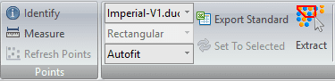
Every ducting element inside of EdgeWise must be based on a standard size. On the left hand side of the ducting tool bar you will find two drop down menus. These allow you to change which default standard you use, as well as what size you want EdgeWise to extract. Leaving the size on Autofit will tell EdgeWise to find the closest size.
If you’d like to insert your own custom standards refer to the custom standards guide found here.
Semi-Automated Extraction
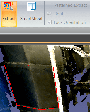
Once your standard and size have been chosen, you can proceed to extract an element. If you would like EdgeWise to determine the size for you, leave the size on Autofit. Select your Extract tool from the ribbon, or press the X key on your keyboard. Now, left click to start your selection box and continue left clicking around your object. When the polygon surrounds the item you would like extracted, double click to finish the selection. EdgeWise will proceed to find the best fit for the ducting element and extract it. Keep in mind, for rectangular Ducting you only need to extract out the straight portions of the duct. Elbow and transition insertion will be done automatically later.
Refer to this article for more information on Semi-Automated Extraction.
QA
To QA an element, select it in the 3D view, then click the SmartSheet button. Alternatively, you can press your Q key on your keyboard. Left-click and drag the white outlined object in the 2D view to adjust its position in 3D space. Take advantage of the other QA translation tools available in the toolbar and in the 3D view.
Refer to this article for more information on QA.
Alignment
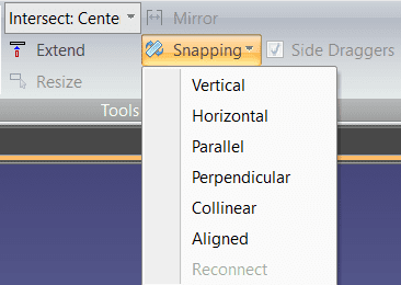
Before you can make elbow connections or transitions, your duct chain needs to be aligned. Performing alignment is done with the Snapping tools found in the ducting toolbar. End pieces of duct chains must be snapped parallel to each other, while the whole chain must be snapped to being aligned with itself.
Refer to this article for more information on Alignment.
Connection
Once your duct chain is aligned you can make use of the Radius Elbow or Mitered Elbow automatic tools.
First use ctrl-left click to select two straight duct sections. Next, if there also needs to be a transition, check the Add Transition checkbox. Lastly, click either Radius Elbow or Mitered Elbow, and EdgeWise will insert the correct elbow.
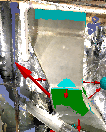
The elbow extracted can then be edited using the red arrows.
Refer to this article for more information on Alignment.
Export
After your model is completed, you’ll be ready to take your model into your deliverable. Click the Export to Revit button or the various options in the Export drop-down menu for your preferred format.
Refer to this article for more information on Exports.