Search Knowledge Base by Keyword
Getting Started
This article will cover how to Export your EdgeWise pipes or structure to PDMS. There is a dedicated plugin that allows for a user to export from EdgeWise into PDMS. This article will cover both the installation of this plugin as well as how to actually utilize the plugin for importing your geometry. For more information on the Piping and Structure workflows start here for piping and here for structure.
Install the PDMS Plugin
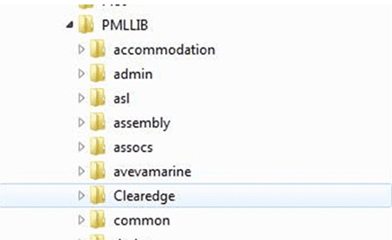
Extract the folders from the provided ZIP file and copy the Clearedge folder to your PMLLIB directory in your AVEVA PDMS server or workstation install.
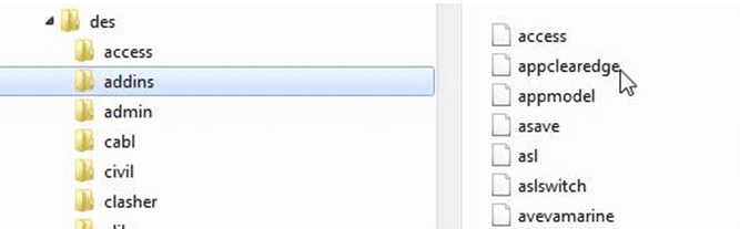
Copy the file from PDMSUI\DES\ADDINS to the PDMSUI\DES\ADDINS directory in your AVEVA PDMS server or workstation install.
If you have local workstation installations, this will need to be done for each workstation. For network licenses, copy the required files and folders to your network location.
After you have installed all files and directories, start PDMS and enter MONITOR to rehash the PML indexes. At the command line in MONITOR, issue the command PML REHASH ALL, followed by PML INDEX. This will update the PML Index files with the path and filenames for the Import Application.
NOTE: If the PML indexes are not update after installation entering DESIGN will cause UI initialization failure.
Export Pipe Model from EdgeWise to PDMS
Create the pipe model within in EdgeWise. Next, ensure you select the model in the model selection pane. Finally, navigate to the File tab, click the Export drop down, hover over Pipes and click PDMS. This will create a .PDMS file.
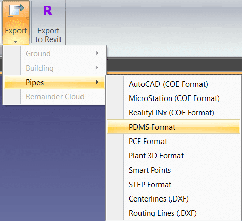
NOTE: You MUST Standardize the pipe model before your export to PDMS (apply ASME/DIN/ standards to the pipes); only pipes with standards will be able to export to PDMS.
Import Pipes into PDMS
The Clearedge3D application will add to the Create Menu for Pipework in DESIGN.
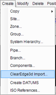
Selecting the ClearEdge3d Import option from the pull down menu will display the main application form.
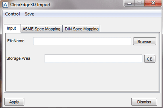
The main form has multiple tabs:
- Input – Contains the Filename input field and the location within the PDMS hierarchy that the imported pipes will be created.
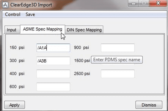
- ASME Spec Mapping – This is used for mapping PDMS spec names to ASME pressure classes that are passed within the import file.
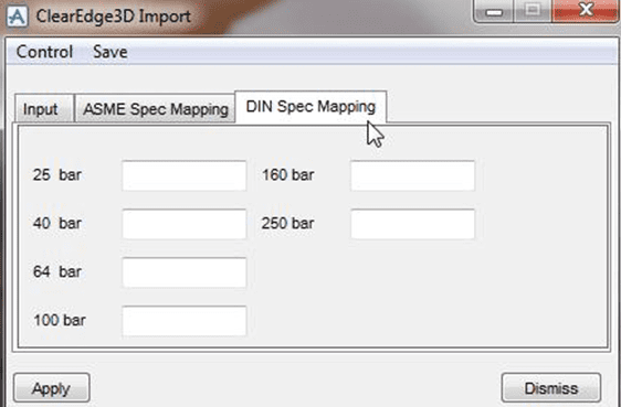
- DIN Spec Mapping – This is used for mapping PDMS spec names to DIN pressure classes that are passed within the import file.
Spec Mapping – Piping
The import data from CleareEdge3D can identify standard pressure classes for both ASME and DIN. You will need to map these pressure classes to PDMS specifications in order to create pipes within PDMS.
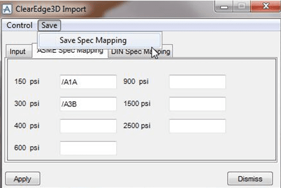
Once you finish mapping the pressure classes to PDMS specifications you will need to save the mapping which will initialize the main form. You will only have to do this operation once. If spec mapping changes, the mapping will need to saved again.
We highly recommend you create a set of generic specs for each pressure class as opposed to using production specs. This will prevent the user from having to select individual components during the import process.
NOTE: We strongly recommend that you use variable angle elbows for all bore sizes. Because the scan data can vary in accuracy, standard angle elbows of 45 and 90 will not work very well. In order to get the pipe route as accurate as possible, the use of variable angles is almost required.
The supported element TYPE and spec STYP are as follows:
- ELBO – EL90 (Variable angle for all bore sizes)
- TEE
- VALV – GATE, VALV – GLOB, VALV – BALL, VALV – PLUG
- REDU
- FLAN – WN
- FLAN – FSO (Slip On flange used to represent LAP JOINT)
- ATTA – AT (Used for termination of pipe tail.)
Piping Known Issues
PDMS will create an Import Error Log during the processing of the data from EdgeWise. The log is located in the home directory of the user as identified by the environment variable PDMSUSER. The name of the error log is clearedge_import_errors.txt. This log gives valuable information that can help troubleshoot any import issues that may arise, such as:
- Multiple branches within pipes will not connect.
- Reducers are currently not identified as to type ie CON ECC.
- The importer does not support Tee and Valve orientation.
- Element positions are based off of SCAN origin.
Export Structure Model From EdgeWise to PDMS
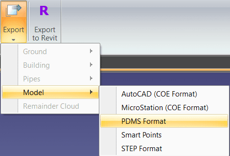
Create the structure model within EdgeWise. Next, ensure you select the model in the model selection pane. Finally, navigate to the File tab, click the Export drop down, hover over Model and click PDMS. This will create a .PDMS file.
Import Structure into PDMS
Enter PDMS DESIGN and select the Structures Beams and Columns application. Then use the Import SCTNs pulldown under the Edgewise menu. This will display the main Application form.
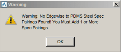
This form has three tabs; Import, File Read Results, and Edgewise to PDMS Steel Specifications. The “Import” and “File Read Results” tabs will be discussed later. If the user has not created any Edgewise to PDMS Spec Pairings, a Warning Message will appear and require the user to click “Ok” as shown below:
Structure Import – EdgeWise to PDMS Steel Specifications Tab
When the main form is shown, the third tab, Edgewise to PDMS Steel Specifications will be visible as shown below.
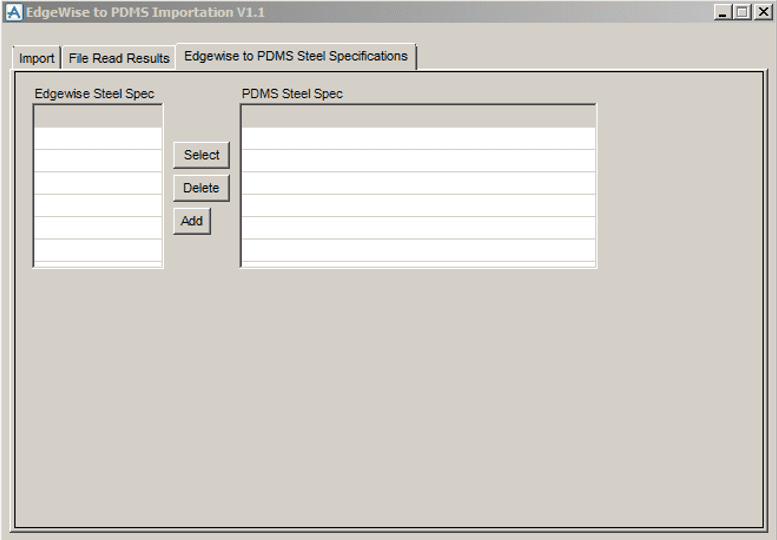
The user cannot read any files or import any steel SCTNs until at least one Steel Spec Pairing is created. The user can add an Edgewise Steel Spec by clicking the Add button which brings up an Input Form as follows:
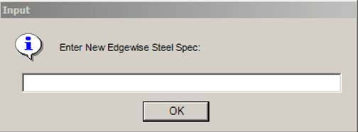
Here, we’ve input the name AISC:
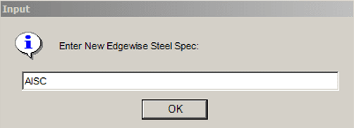
Press OK and the following form appears:
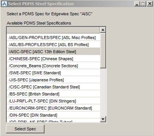
This form lists all of the PDMS Steel SPECs found in the current PDMS project and also shows the DESC attribute of the SPEC in square brackets (“[]”). For the user’s PDMS Steel SPECs to show up, the PURP attribute of the SPEC must be set to STL. It is also helpful to set the SPEC’s DESC to something meaningful. The SPECs seen in each of the user’s projects will be different from what is seen here. I moved to the project’s only AISC SPEC and pressed the Select Spec button.
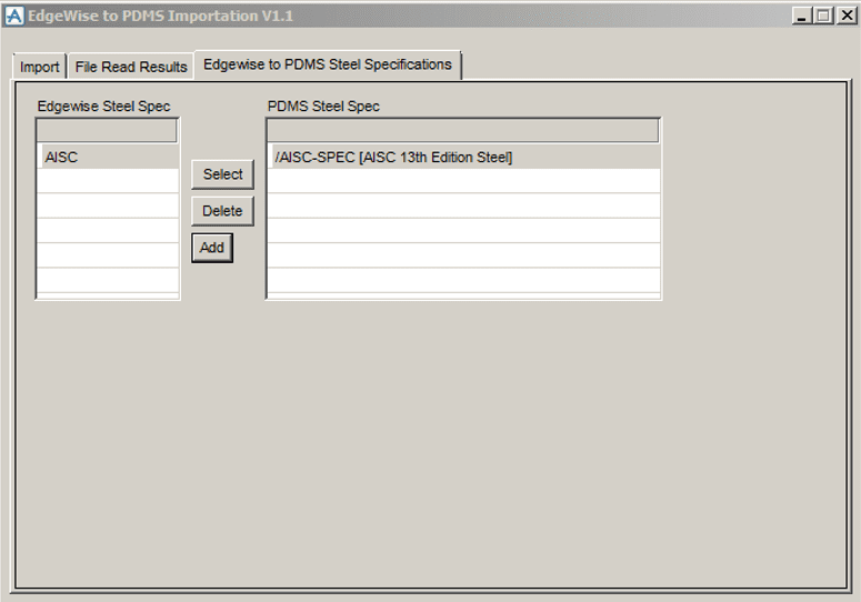
The user can add an Edgewise Spec , delete a Pairing, or reselect a PDMS SPEC at any time. This data will store in a text file named EdgewiseToPDMSSTLSpecs.txt in the PDMS Project folder that the user is in. If the user creates a bad Edgewise to PDMS Spec Pairing, the SCTNs’ PDMS SPREFs will not be found and the user will need to select a different PDMS Spec. Once you create at least one Edgewise to PDMS Spec pairing, the user can proceed to the Import tab.
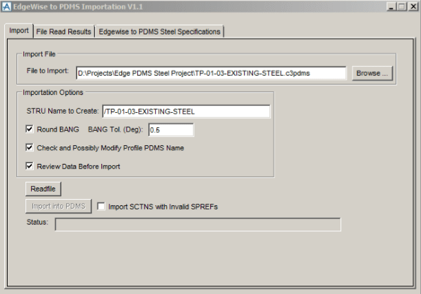
Structure Import – Import Tab
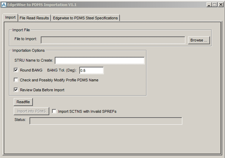
The Import tab allows you to control which .c3pdms file to import, the STRU name to create/replace, if you want to round SCTN BANG values, if you want to apply Profile Name modifications, if you want to review the file read results before you import into PDMS, and if you want to import SCTNs with invalid SPREFs.
The Browse button brings up a PML file browser that allows you to navigate to the .c3pdms file you wish to import. When you select a .c3pdms file and click the open button, the file name minus the file extension will convert into a PDMS name by replacing spaces with underscores and adding a beginning “/” character. If this name already exists, you will receive a warning message that allows you to either overwrite the existing STRU or change the STRU name. To change the STRU name, enter the desired name in the STRU Name to Create box and press the enter/return key. This will check the name against existing named objects in the PDMS Project.
The Round Bang Check Box and BANG Tolerance value allows you to round the SCTN BANG values to the closest 45 degree angle (0, 45, 90, 135, 180 and the negatives of each) if the BANG is within the specified tolerance. This rounding is done during the Readfile process (before the Import process).
Structure Import – Import Tab – Cont.
The Check and Possibly Modify Profile PDMS Name Check Box controls the calling of a user-modifiable PML Function which can check and change the Edgewise Profile Name to a valid PDMS SCTN CATREF Name. For instance, some PDMS users use lowercase ‘x’s rather than uppercase ‘X’s (W12x26 vs W12X26). If the user wants to not check/modify the profile names, simply leave this Check Box unchecked. Otherwise, check it, and modify the PML Function as desired. This checking is done during the Readfile process (before the Import process). Please refer to Section User Customization for more details.
The Review Data Before Import checkbox allows the user to see the Readfile results before import into PDMS. Checking this box is the recommended approach as it allows the user to review and possibly change SCTN profiles before importing them into PDMS. If you do not check this checkbox, the Readfile process is followed immediately by importing the SCTNs into PDMS.
The Import SCTNs with Invalid SPREFs checkbox controls the importation of SCTNs with invalid specification references. If the user wants these SCTNs imported (they will show up as dashed lines in PDMS), the user should check this checkbox. If you do not check this checkbox, the importer will ignore SCTNS with invalid specification reference and will fail to import them into PDMS.
The Readfile and Import into PDMS buttons are self-explaining (see checkbox controls above). Here is the form after selecting a file to import:
Structure Import – Read File Results Tab
The Read File Results tab shows the Readfile process results and allows the user to review and possibly edit SCTN profiles. If you check the Review Data Before Import checkbox, pressing the Readfile button switches to the File Read Results tab after reading the file as shown below.
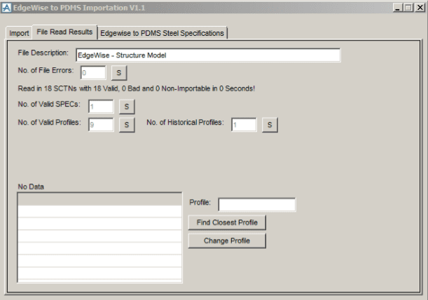
The File Description references the file you select and will import into PDMS as the DESC Attribute of the named STRU from the Import tab and is editable.
The No. of File Errors indicates the number of errors handled when reading the selected file. If there are any, clicking the “S” (Show) will display the errors in the No Data list below.
The next line shows the total number of SCTNs read in and the number of valid, bad, and non-importable SCTNS found.
The next field is the number of valid Steel Specifications in the file. The user can add any Steel Specification that Edgewise supports by using the third tab Edgewise to PDMS Steel Specifications.
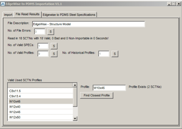
The next field is the No. of Valid SCTN Profiles. Clicking the S button will populate the list below as shown in the next picture. Clicking on each profile will in turn display the profile’s status and the number of SCTNs using that profile.
Structure Import – Valid Used SCTN Profiles
In the form below, notice that the list shows Profile Names modified to conform to our PDMS AISC Catalog (lowercase ‘x’s).
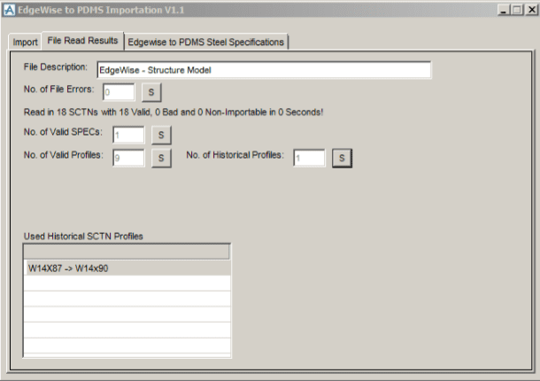
The next form shows the results of showing the ‘Historical Profiles’. Since our PDMS AISC Steel Catalog is based on the 13th edition, it does not contain a W14X87 (or a W14x87), so the code looks for the next available profile. This ability to look for the proper profile can complicate the process depending on the Steel Specification and Profile shape (H Shapes, Channels, Angles, etc). See the User Customization and Known Issues and Limitations Sections.
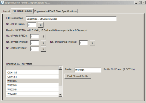
As stated earlier, the user can modify each the Profile Names via the Check and Possibly Modify Profile PDMS Name function or manually. The next form shows the same input file but read in with the Check and Possibly Modify Profile PDMS Name Check Box unchecked. The Unknown SCTN Profiles list will display by clicking the S (Show) behind the No. of Bad Profiles. Here, the user has clicked on the W10X45 and the form indicates the Profile was not found and that it is used 2 times.
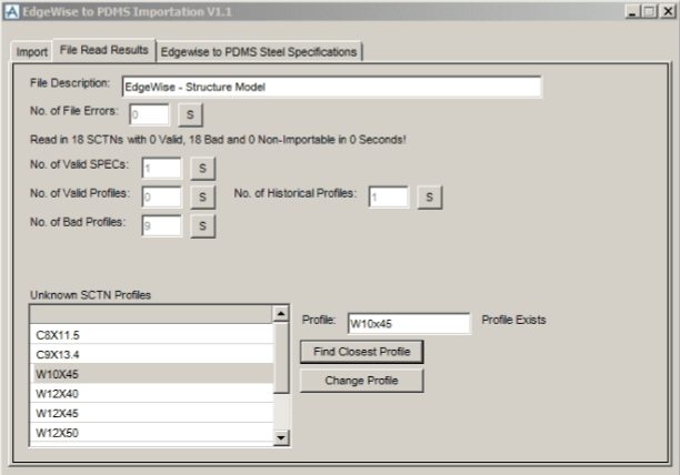
If the user changes the “X” to an “x” and presses the Enter/return key, the form changes as shown below. Since this Profile exists, the form displays the ability to change the Profile name for all SCTNs that use this profile. Since this “mapping” is not saved, the next file that has the original Profile name will require the user to repeat this edit. See the User Customization and Known Issues and Limitations Sections.
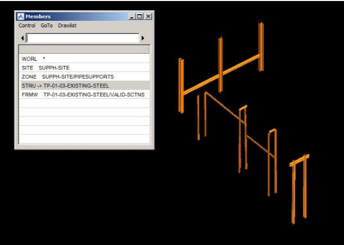
Finally, here is a portion of a piperack in PDMS after import:
User Customization
Since none of the PML files are encrypted, you have the ability to modify the entire import process. We suggest you limit your modifications to the two PML functions “!!editedgewiseprofile” and “!!getclosestprofile “. This will allow Edgewise to add features in new releases and allow the user more control of their import process.
The first function (“!!editedgewiseprofile”) takes two parameters (the Edgewise Steel Specification Name and the Edgewise Profile Name) and returns the (possibly) modified Profile Name. It is used to modify the Profile Name to something compatible with the PDMS Project’s Steel Catalog. The user can use these two parameters (and can even use the PDMS Project Code if needed) to filter and make whatever changes desired to the passed-in Profile Name.
The second function (“!!getclosestprofile”) also takes two parameters (the Edgewise Steel Specification Name and the PDMS Profile Name) and possibly returns the Profile Name of the next larger SCTN. It is used to find PDMS Steel Profile Names matching whatever part of the passed-in Profile Name the user desires and tries to return the next Largest Profile Name.
Known Issues and Limitations
- Non-orthogonal PDMS SCTNs are sensitive about the BANG values and the POSS and POSE values. Because of this, we suggest that you use the SNAP BEAM option in Edgewise on all applicable Steel Shapes before you Export the structural model(s).
- All SCTNS will import with the PDMS JUSL Attribute = NA. This condition may not be friendly to other downstream PDMS processes.
- SCTN BANG values will often need adjusting after the import process even when using a the Round BANG Check Box with a large BANG Tolerance
- Often times the names of the various Steel Profiles will vary between Edgewise and PDMS. This may be because of differences in Steel Spec versions, PDMS Steel Catalogs being out of date, user preferences, etc.